
Skip to content

Selected engineering work

Find the cause.
Define the next step.

What the client needed. What the evidence showed. How the engineering helped.

01 / Origin and cause · Slope and structure

Finding the cause behind a hillside failure

Property owner's insurance carrier

Oʻahu, Hawaiʻi

KMF Engineering assignment

The request

Determine why the slope and boundary structure failed, separate the contributing causes, and identify the immediate hazards and repair priorities.

Why it mattered

A failure described as a retaining-wall collapse required more than a replacement estimate. The parties needed to understand the ground movement, the structure's actual function, and what needed to happen first.

The causal explanation

  1. 01

    Rainfall-driven erosion removes support from susceptible slope soils.

  2. 02

    Ground movement exposes and undermines the boundary-fence supports.

  3. 03

    Limited embedment and deficient reinforcement contribute to failure as ground support is lost.

How KMF helped

KMF gave the insurer an origin-and-cause report separating the slope mechanism from deficiencies in the boundary fence. Immediate guidance prioritized unstable material and loose debris, which the report records were subsequently removed. Restoration recommendations addressed the ground and fence as separate parts of the loss.

A damaged concrete-and-timber boundary fence stands above an eroded slope, with its supporting grade beam exposed.
The overall failure: erosion exposed the fence's supporting structure. KMF distinguished the fence from a retaining wall and assessed the slope separately.
Exposed soil and roots beneath a concrete grade beam reveal a short embedded support below the failed fence.
The critical detail: the exposed support and undermined beam helped explain how the fence lost support when the ground moved.
Read the engineering analysis

Evidence & reasoning

A failure reported as a retaining-wall collapse was examined as two connected problems: why the ground moved, and how the structure behaved when its support was lost. KMF reviewed the site, available geotechnical information, survey records and rainfall history. The investigation identified rain-related erosion of susceptible slope soils and distinguished the concrete-and-timber boundary fence from a structure designed to retain earth. Exposed supports, undermining, weak concrete and inadequate reinforcement detailing helped explain the fence failure. That distinction mattered: the replacement scope had to address both the ground conditions and the fence's actual function. KMF separated immediate hazards from longer-term restoration and recommended removal of unstable material, restoration of the slope profile and vegetation, and appropriate replacement of the boundary fence.

Work delivered

  • Origin-and-cause engineering report
  • Immediate hazard-removal guidance
  • Recommendations for slope and fence restoration
02 / Construction support · Water intrusion

From a leaking lanai to a controlled repair plan

Contractor

Oʻahu, Hawaiʻi

KMF Engineering assignment

The request

Find the water-entry mechanism, evaluate the affected structure, and provide the contractor with a shoring and releveling plan for the repair work.

Why it mattered

Water damage below a roof lanai came with softened timber, displaced finishes and visible structural movement. The contractor needed to understand the damage and support the framing in a controlled sequence before replacing components.

The causal explanation

  1. 01

    Unprotected deck penetrations allow water into concealed assemblies.

  2. 02

    Repeated moisture exposure deteriorates timber and damages finishes below.

  3. 03

    Deformation of the framing makes structural support and controlled releveling part of the repair.

How KMF helped

The contractor received the assessment, a written shoring sequence and a project-specific shoring plan. Follow-up correspondence addressed equipment selection and control of movement as the framing was brought toward its target elevation. That package translated the diagnosis into a sequence the contractor could coordinate with demolition and structural repairs, defining support requirements while damaged components were exposed and addressed.

An opening between timber guardrail-post members at a tiled lanai deck exposes a water-entry path below the surface.
The entry path: an open, unprotected post base penetrated the tiled deck and provided a route for water into concealed construction.
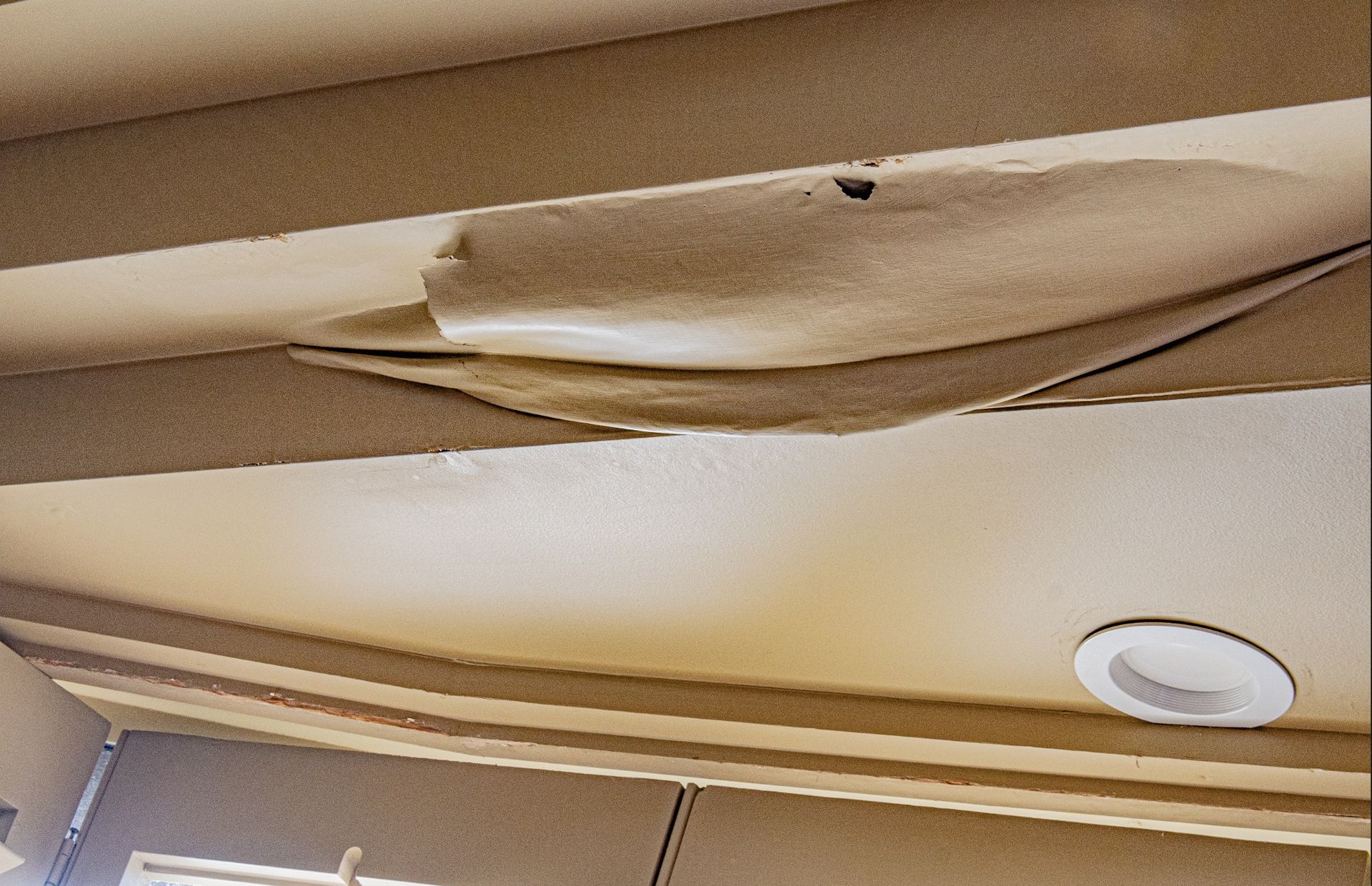
Buckled and detached ceiling finish beneath the lanai shows damage within the occupied space below.
The consequence below: damaged ceiling finishes helped connect the deck-level findings to water intrusion inside the building.
Read the engineering analysis

Evidence & reasoning

A leaking roof lanai had become a structural-repair problem. KMF followed the water path from untreated timber guardrail posts that passed through the tiled deck without visible flashing or a continuous moisture barrier. Openings at those bases provided a route into the deck assembly and the rooms below. Moisture readings, softened timber, water-damaged ceiling finishes and visible deformation of supporting members were evaluated together with the available building plans. The assessment connected concealed moisture exposure to deterioration and movement of the structure, including changing floor slopes and splits. The contractor needed a plan for exposing, supporting and releveling the framing before replacing damaged members. KMF developed a shoring layout and staged sequence addressing support locations, elevation control, jack engagement and the order of repair operations.

Work delivered

  • Water-intrusion and structural assessment
  • Written shoring sequence
  • Shoring layout and repair-stage support details

03 / Construction damage · Forensic investigation · Expert support

When containment failed, the damage crossed the property line

Legal counsel

Hawaiʻi

KMF Engineering assignment

The request

Provide expert engineering support for counsel evaluating damage to an occupied property beside a demolition project.

Why it mattered

Establish how construction debris and runoff reached the neighboring building, why the protection failed, and what effective protection would have required.

The causal explanation

  1. 01

    Masonry demolition produces falling fragments and fine material.

  2. 02

    Wall-side gaps and damaged netting allow material to reach the adjoining roof and canopy.

  3. 03

    Impact-compromised surfaces admit slurry into the occupied building.

How KMF helped

Counsel received an expert report connecting demolition activity, failed containment and neighboring-property damage. KMF identified why the installed protection was inadequate and what safeguards the work required. Those specific mechanisms and supporting evidence gave counsel a technical basis to evaluate and present the claim.

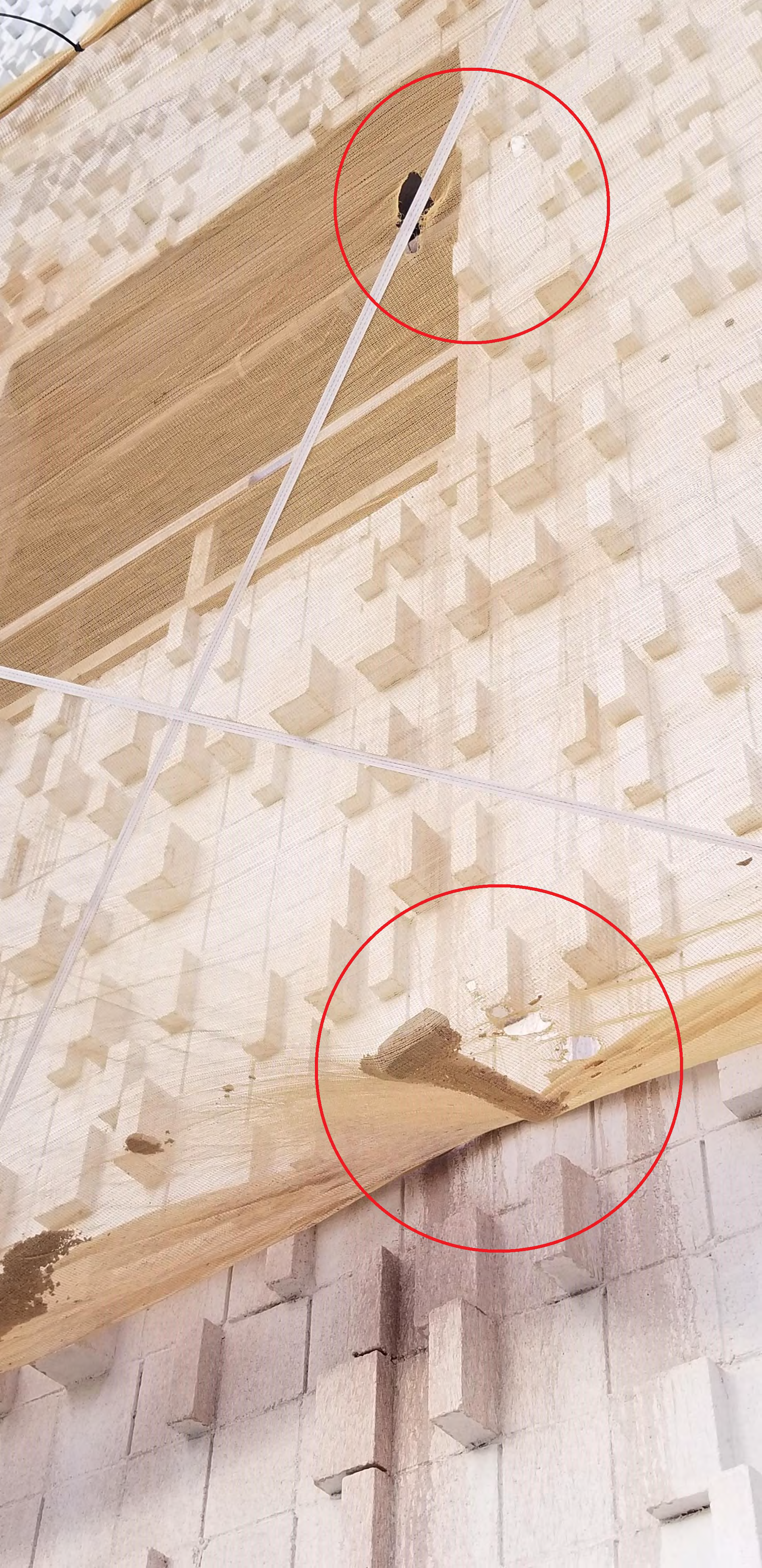
Upper detail of a project photograph showing a tear in construction containment netting.
The breach: a project photograph reviewed by KMF shows a tear in the containment net. The red annotation is part of the source exhibit.
Lower detail of the same project photograph showing masonry debris caught at the lower edge of the containment net.
The escape path: the lower detail shows masonry debris at the net’s interface with the adjacent wall. KMF evaluated whether the protection suited the work.
Read the engineering analysis

Evidence & reasoning

KMF connected the damage inside the neighboring building to the demolition work above it. The investigation combined an earlier site inspection with construction records, photographs and deposition testimony. Large masonry fragments had reached the roof and atrium canopy; the report linked those impacts to compromised roof and canopy surfaces that allowed demolition slurry into the occupied space. The key issue was the entire protection system: gaps at the wall and tears in the netting allowed debris to escape containment. KMF examined those details against the construction sequence and the site's access constraints, then evaluated engineered netting, catch platforms and roof protection as alternative safeguards. The resulting opinion explained both the physical damage pathway and the shortcomings in planning protection for the adjoining property.

Work delivered

  • Review of construction photographs and discovery records
  • Engineering analysis of containment and property protection
  • Expert report and technical support for counsel

04 / Water intrusion · Building envelope · Repair planning

Finding the cause of a leak that kept coming back

Homeowners

Hawaiʻi

KMF Engineering assignment

The request

Find the source of recurring leaks below an upper lanai and identify what needed to be repaired.

Why it mattered

The homeowners needed a causal explanation for damage that earlier inspections and repeated attempts to manage the leaks had not resolved.

The causal explanation

  1. 01

    Deficient waterproofing at the deck and railing allows repeated wetting.

  2. 02

    Timber deterioration develops behind painted surfaces and within the structure.

  3. 03

    Sagging disrupts drainage and joints, allowing further water entry into rooms below.

How KMF helped

The homeowners gained a documented explanation for leaks they had struggled to resolve. They later asked to share KMF's report with their repair contractor and counsel, specifically crediting the investigation with pinpointing the cause. The report gave them a repair scope tied to that cause: remove the upper deck, expose and repair damaged framing, and rebuild the waterproofing and drainage details. It also identified the railing condition requiring immediate attention.

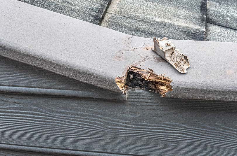
Deep wood decay exposed beneath the painted cap of a lanai railing.
Paint concealed deep decay in the railing cap. The condition beneath the finish explained why surface treatment alone could not restore the wood.
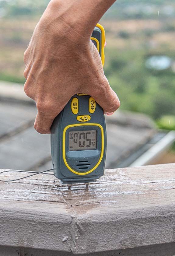
A handheld moisture meter probes the painted timber railing.
Field moisture testing helped assess the timber beneath the painted surface, alongside probing and observations during rainfall.
Read the engineering analysis

Evidence & reasoning

KMF traced the interior damage back through the lanai assembly. The inspection combined visual assessment, probing of concealed spaces and field moisture testing. Rain during the visit exposed an active route: water permeated a structural beam and dripped into the bathroom below. Painted railing components concealed deep wood decay, while sagging gutters held water instead of draining. The findings connected these observations into a progressive failure mechanism. Inadequate protection at the deck and railing admitted water, repeated wetting deteriorated the wood, and the resulting movement disrupted joints and drainage, creating further entry paths. The report also identified a separate immediate concern at deteriorated railing-post connections. Repair recommendations therefore addressed waterproofing, damaged framing, connections, slope and drainage together, with restriction of deck use until the railing was secured.

Work delivered

  • Site inspection and moisture measurements
  • Assessment of water-entry paths and concealed deterioration
  • Engineering report with corrective-work recommendations

05 / Slope movement and structural damage

When the hillside moved, the damage followed.

Property insurer

Oʻahu valley property

Prior professional work by Kevin Fitzgerald at J.S. Held.

The request

Determine the cause of damage to a hillside home, its driveway and retaining walls, and document the engineering findings for a property-loss claim.

Why it mattered

The cracking was spread across several structures. The client needed an explanation connecting the visible damage to the moving ground and the pressures acting on the home.

The causal explanation

  1. 01

    Upslope ground and the retaining wall displaced toward the home.

  2. 02

    The narrowing terrace increased soil pressure against the home’s retaining foundation wall.

  3. 03

    The wall turned inward while the driveway fractured, slipped and lost support through scour.

How the work helped

The report connected field measurements and observed damage to a common ground-movement cause. That gave the insurer a documented engineering basis for evaluating the reported loss and clarified why the driveway, retaining walls and house had been affected together.

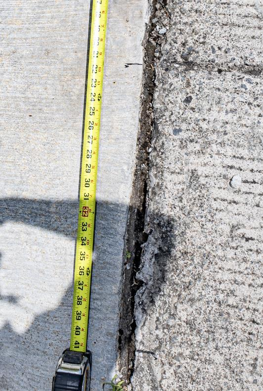
Tape measure beside displaced concrete at a driveway and garage-apron joint.
Nearly 20 inches of relative slip was documented using the owner’s earlier reference marks.
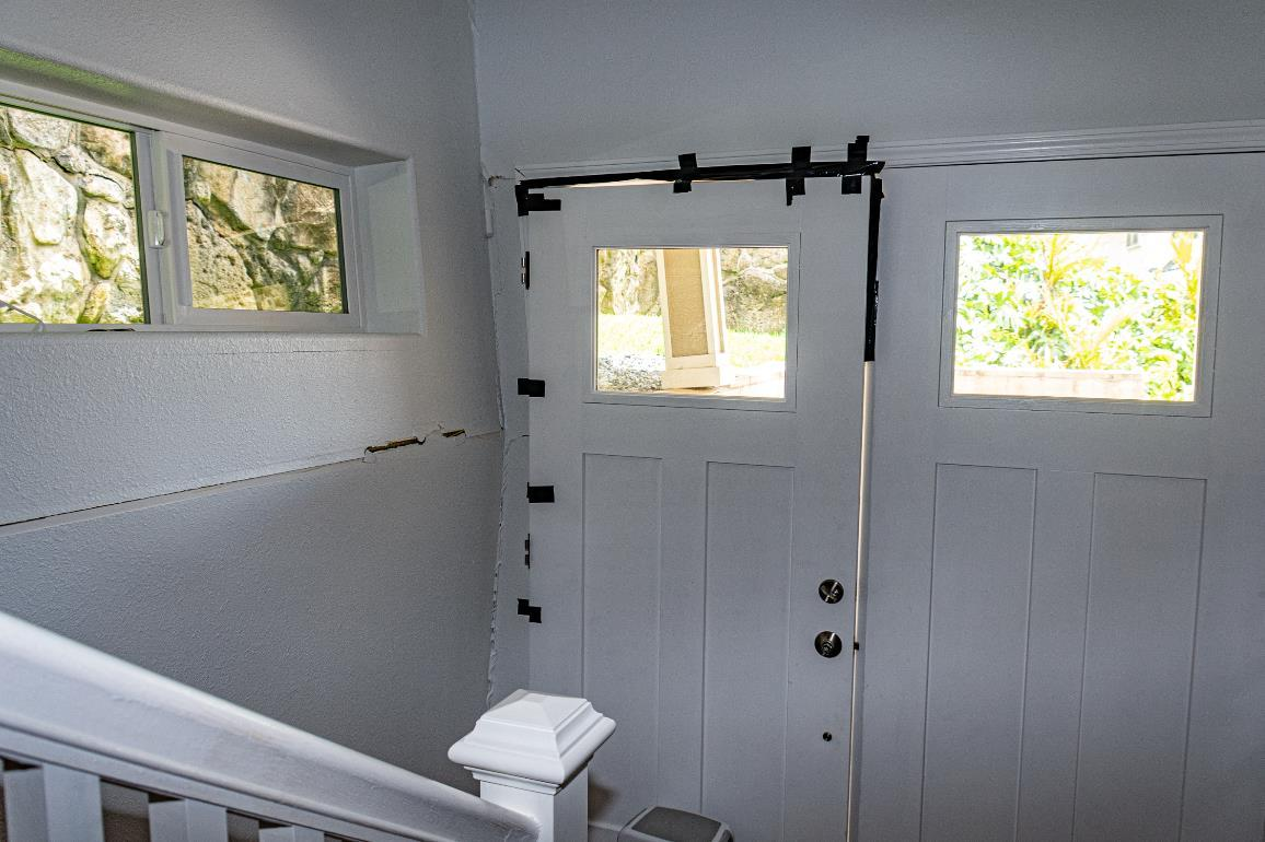
Horizontal cracking in an interior wall beside a distorted entrance door frame.
The inward-moving foundation wall produced horizontal cracking and distortion beside the entrance.
Read the engineering analysis

Evidence & reasoning

Kevin inspected the property and compared damage across the driveway, retaining walls and home. Driveway fractures exceeded four inches, and relative slip at the garage apron measured nearly 20 inches using the owner’s earlier reference marks. An upslope retaining wall had moved toward the home; the remaining terrace measured eight feet, compared with the owner’s reported earlier width of ten feet. The report connected that movement to increasing soil pressure against the home’s foundation wall, which was overturning inward and cracking beside the entrance. Scour beneath the driveway and inadequate drainage and erosion control added to the instability. The resulting explanation was a linked slope-failure mechanism, with earlier creep followed by larger movements, rather than isolated damage to separate building elements.

Work delivered

  • Field inspection and damage measurements
  • Cause determination connecting ground and structure
  • Sealed engineering report

06 / Foundation failure and construction-claim analysis

Tracing sudden rail-foundation movement through the records.

Insurer reviewing a construction loss

California rail guideway

Prior professional work by Kevin Fitzgerald at J.S. Held; document review preserved in working records.

The request

Determine the cause of sudden foundation movement during rail-bridge replacement and examine technical grounds relevant to an insurer’s recovery assessment.

Why it mattered

The client needed the sequence of loading, observed movement and foundation assumptions reconciled, so design and ground-support questions could be distinguished from installation-compliance questions.

The causal explanation

  1. 01

    Girder placement adds major load to the new foundations.

  2. 02

    Monitoring records show abrupt downward movement after major loading stages.

  3. 03

    The working analysis attributes the response to inadequate soil support beneath drilled shafts.

How the work helped

The work organized a large project record into a loading chronology and causal explanation for the insurer’s evaluation of the loss and possible recovery avenues. It distinguished design and ground-support questions from installation compliance, identifying where the available records supported an engineering opinion.

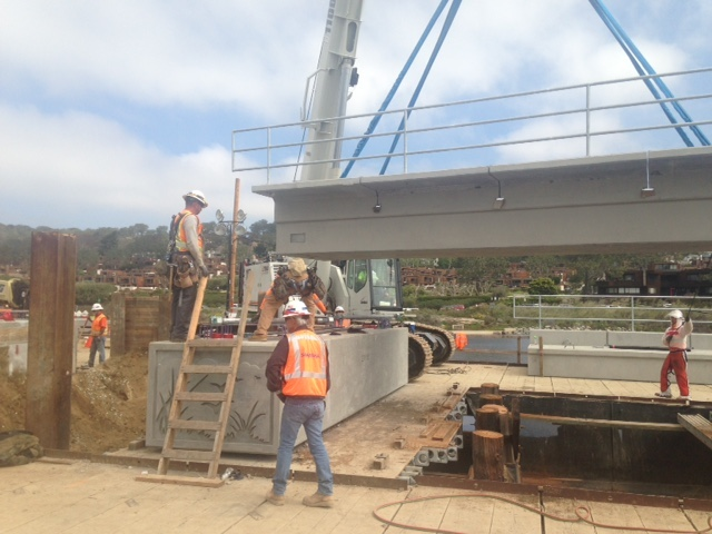
Construction crew setting a precast concrete rail girder onto its support.
A project-record photograph of girder installation helped place major loading activities in the failure timeline.
Read the engineering analysis

Evidence & reasoning

Kevin’s document review aligned settlement-monitoring data with construction schedules, approved work plans, inspection records and staged concrete-girder installation. The records showed abrupt downward movement after major loading stages, including a repeated response when the second stage was installed. He compared the new foundation arrangement with geotechnical assumptions and the depth and distribution of the available borings. Kevin’s working analysis attributed the sudden movement to inadequate soil support beneath the drilled shafts, while identifying gaps in the ground investigation and bearing-capacity assumptions. It questioned whether bearing resistance and subsurface conditions had been adequately established for the design. The installation-record review reported no identified workmanship or specification departures that would worsen the event. This was a reconstruction from records, without site visits or interviews.

Work delivered

  • Chronology of loading and recorded movement
  • Review of geotechnical and construction records
  • Working cause analysis and assessment of installation compliance

These anonymous examples describe the engineering work and decisions it supported. Prior professional work is attributed where shown.

Let’s talk about your engineering question.

Discuss future work